How to synchronize a Biosemi ActiveTwo EEG with a stimulus using audio instead of triggers
When I started my postdoc, my lab had been working on a paradigm where the participant taps a key in rhythm with a metronome in the EEG scanner. All it took was one listen for me to realize that the metronome they had created was not steady, especially for the first few clicks. The problem was that they were generating the clicks on the fly in MATLAB using a “wait” command instead of just playing an audio file — the MATLAB loop was sensitive to variation in processing time, whereas audio file playback is designed for perfect temporal fidelity. But they needed to do the whole thing in MATLAB so that they could send trigger signals to the EEG concurrently with each click that they could later use to time-lock their event-related potentials.
I had never worked with an EEG before, but I knew there had to be a better way. After google-groping in the dark for a little while, I found a few sources like this one that suggested that I create an audio file and use one of the two channels as a synchronization signal to the EEG. As a performing musician, I was much more comfortable with audio signals than with EEG, but I still needed much more detailed instructions than these sites were providing.
Several years later, I am ready to write the instructions that I would have wanted at that time.
This will allow you to present your audio stimulus from a basic media player rather than having to play it from software that can also send trigger signals, and it will allow you to easily create audio stimuli with built-in trigger signals that you can play directly from a media player. You can even play your stimuli from a DAW (digital audio workstation), allowing you to record an audio track at the same time that you play the stimulus. This is great for:
- Tasks where the participant is tapping a finger along with a rhythm: you can record the taps with a microphone and synchronize them with the stimulus with zero lag (more on that in a later post).
- A self-generated sound ERP paradigm: you can have the participant play a MIDI instrument in the DAW that creates both sound and sync signal, and record them so that you can play them back later and compare ERPs to the same sound sequence when the participant is generating it and when they are listening to it (again, more in a later post).
This also works with a video stimulus: just create the audio as described below, and then sync it with the video using a video editor.
Overview
The Biosemi has an “Ergo” input that just happens to perfectly fit a MIDI cable. It will record whatever you put into this port in sync with the EEG. The trick is to use one audio channel for audio stimulus, put square pulses on the other channel at the beginning (and/or end and/or important events) of the stimulus, and pipe that “sync signal” into the Ergo port. I created audio files to this specification in MATLAB.
The devil is in the details: getting it in there is easy, but getting it in there in a safe and appropriate way is not. First, you can’t risk having a conductive path from an electrical socket to the EEG, but sending the signal from a laptop running off battery power didn’t work for us — when the laptop wasn’t grounded, we ended up with static electricity problems that contaminated our finger-tap recordings. Instead, we turned the audio signal into an optical signal and then back into audio before it got to the EEG.
Second, you need a special circuit to turn the audio into a “differential” input that is friendly to the BioSemi device. I think BioSemi sells things that can do this for you, but the circuit is just a couple of resistors, and we had everything we needed to set it up solder-free lying around in the lab.
Diagram
Path from stimulus computer to EEG:
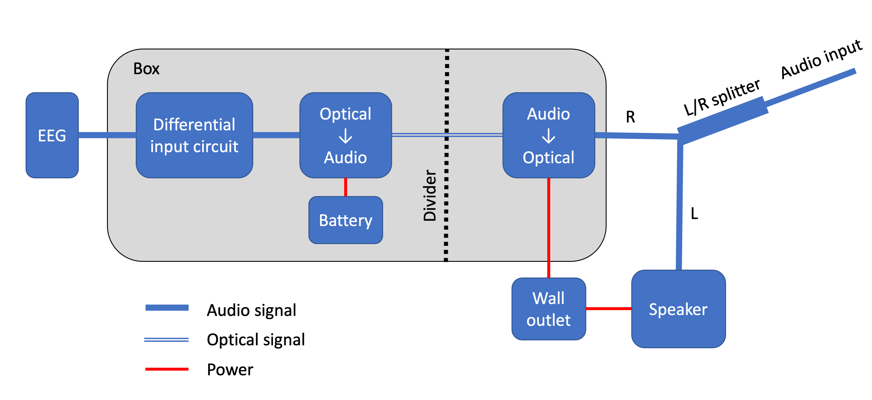
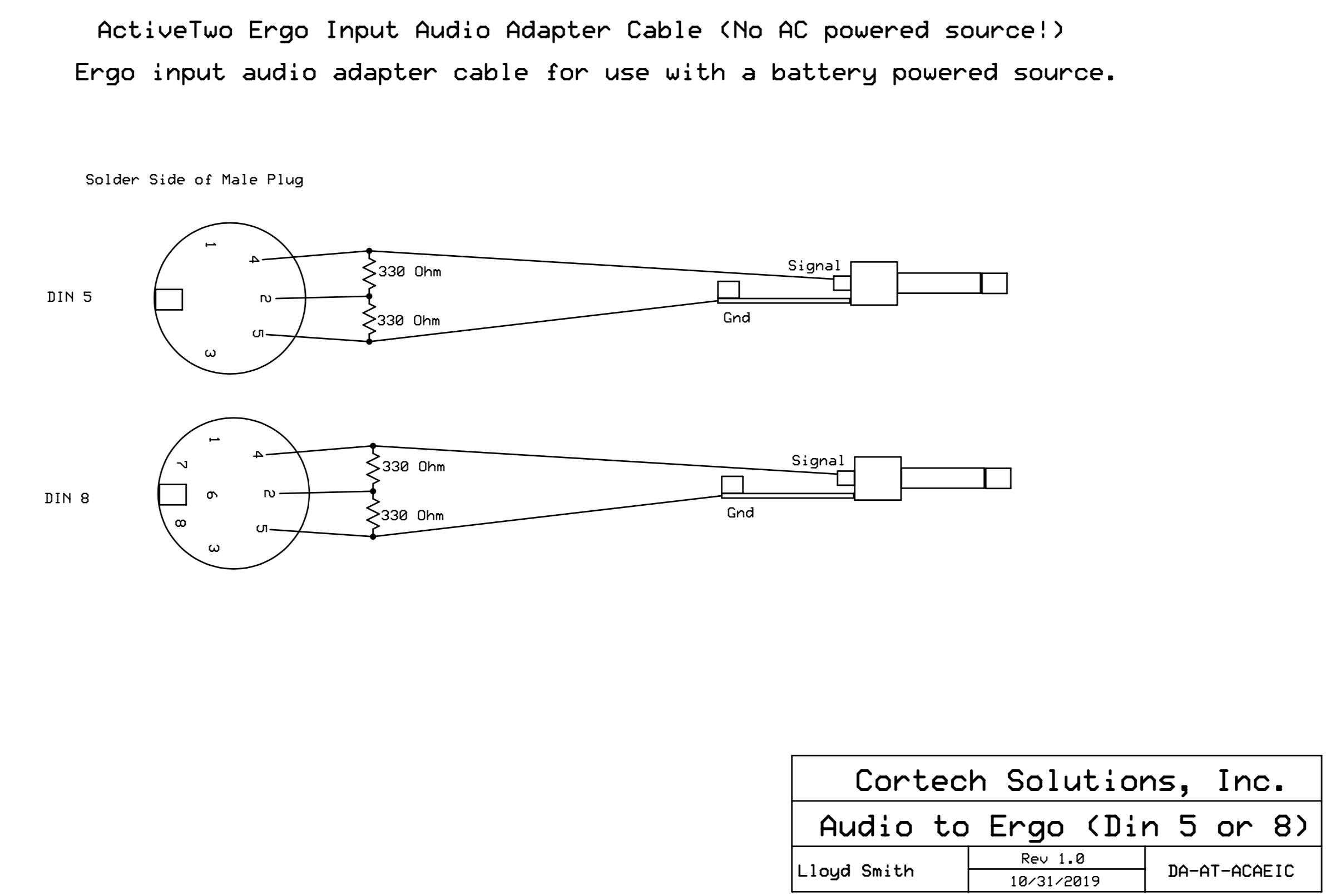
Schematic of the “differential input circuit”:
Details
Use 1/8″-1/4″ adapters as needed along the way, noting that these come in both mono and stereo flavors.
Audio input: The stimulus computer is hooked up to a simple audio interface, e.g., the Focusrite Scarlett 2i2. You can plug the splitter directly into the output from the “headphone” port, which carries a stereo signal with both the left and right channels.
L/R Splitter: Also called a “stereo breakout cable.” I suggest the “Hosa YPP-117 1/4″ TRS to Dual 1/4″ TSF Stereo Breakout Cable.” Note that an ordinary headphone splitter will not work here – it needs to split the left and right channels into two separate outputs.
Audio -> Optical: Find one with a 1/8″ input unless you want to convert the signal to RCA. I suggest the “Hdiwousp Analog to Digital Audio Converter.” Note that this can receive wall power because there is no conducting path from here to the participant’s head. Just in case, I separate this device from the rest of the box with a barrier. These guys usually come with an optical cable.
Optical -> Audio: I suggest the “eSynic 192KHz DAC Converter with 3.5mm Jack and RCA.” Note that this should NOT receive wall power – instead, it is attached to a rechargable USB battery. Make sure that this device’s power supply is USB so it can plug into the battery.
Battery: Any rechargable USB battery should work. I used the “UGREEN Portable Charger 10000mAh.” HOWEVER… note that some batteries (including this one) go to sleep automatically if the device plugged into them isn’t drawing much current, and the Optical -> Audio converter doesn’t draw much current. I solved it by plugging a USB powered reading lamp into the second USB port. When the lamp was on, it drew enough power to keep the battery on. Silly but effective.
Differential input circuit: Biosemi can probably sell you this device, but it’s not hard to build on a breadboard if you have a few audio cables you can dissect (see circuit diagram above). Note that by some stroke of luck, old-fashioned MIDI cables end in 5-pin DIN plugs that fit right into the ActiveTwo Ergo input, and they’re even connected to the right three pins! I happened to have picked up such a cable at a yard sale years ago for no discernible reason, and it had a clear casing so I could see which wire went to which pin. If you’re good with solder, you can just buy the plugs and wire them up yourself; if you’re not, you can buy a MIDI cable and a 1/4″ mono cable, cut them, strip them, and feed them into the breadboard as appropriate.
Stimulus generation: I built the audio stimuli as .wav files in MATLAB. Every sound file’s R channel started with a series of two short pulses and ended with three short pulses (pulse duration and pulse spacing both equal to three EEG samples at 512 Hz, amplitude 0.04, though this will depend on system volume). In between, each sound played on the L channel was accompanied by a pulse at the onset time in the R channel. One drawback of this method is you can’t easily send a “trigger code” distinguishing one event from another, but you can just save a file that lists the event codes in order that you can use as a key.
Decoding the sync signal: Using EEGlab in MATLAB… every time the recorded Ergo signal exceeded a threshold, I checked how many pulses there were following it, and then recorded either a start event, end event, or sound event at that timepoint. I used the key file to label each sound event with its specific sound identity. I formatted these timestamped events the same way that EEGlab formats its event lists, and then I subbed it in for the event list before continuing with EEG analysis — see EEGlab documentation for details on how events are represented.